After the last changes, our prototype begins to get a (very far) appearence of a real computer. We have a central processing unit that executes code, we have a non-volatile memory where we have stored our program, we have a RAM to which the CPU reads and writes data, and we also have a peripheral that interacts with the external world. Today we will add another peripheral chip, a Z80 CTC, a programmable counter/timer that can be very useful in several situations.
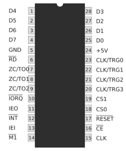
A counter/timer is a peripheral that can count external signales (counter) or meauseres a time (timer). We can use a timer to tell the CPU to execute a specific subroutine once a certain period of time. Or, maybe, raises an interrupt signal after a a specific number of impulses arrived at the chip. We can instruct the CTC to generate a signal on a pin at a specific frequency. The measurement of time is an important task of any computer: the programmer can use the elapsed time to set delays in his/her softwares, schedules tasks to be executed at fixed hours or once a certain elapsed time, to keep a simple calendar and so on. Some computer designers of the past, to keep costs as low as possible, didn’t use any specific hardware for this tasks, so programmers had to use what has been included in the system: i.e., the MSX users used the interrupt raised by vertical retrace signals in the video processor, that occured 50 or 60 times per seconds (dependind on which type of chip the computer had, if PAL or NTSC), while the Commodore systems had this function as a built-in features. Modern microcontrollers usually integrate one o more timers/counters that can be programmed for a lot of tasks: but old CPUs didn’t have such integrated peripherals so they had to lean on external hardware. Zilog made a very good chip, the Z80 CTC. It has 4 programmable timers that can be run by internal or external clocks: in the latter they act as counters, counting how many impulses they receive on their pins. This is the pinout of the chip:
As you can see, it’s another member of the Z80 family, so it can be connected directly to our Z80 with no additional components. It only needs the wiring of the Z80 main signals (like IORQ, M1, etc.) and to be connected to the data bus:
- D0..D7: data pins
- /RD: to select a read/write operation
- /IORQ, /M1, and CLK: to the corresponding pins of the CPU
- /RESET: to the system reset line
- CS0 and CS1: used to select the timer to interact with – usually connected to A0 and A1 of the CPU
- /CE: the chip enable pin. We will connect it to our 74139 peripheral decoder
The interrupt pins (/INT, IEI, and IEO) are used only if the Z80 interrupt daisy chain is used: if not, you can leave them unconnected or use only the /INT line if you think to use the interrupt feature.
How does the CTC work? It has 4 internal units (Timer 0 to Timer 3) that can be programmed as timers or counters: they can be clocked by the system clock or by an external clock on the corresponding CLK/TRG pin. When the register reaches zero, the timer sends an external signal on its ZC/TO pin and, at the same time, reload the starting value (this features can be set or not). The timer can also raises an interrupt signal: if the chip is inserted into the Z80 interrupt daisy chain function and the CPU is operating with interrupt mode 2, the CPU can execute an interrupt service routine at a specific address. Otherwise, a generic INT interrupt will be raised and it will be the programmer to manage this interrupt in the right manner. As you can see by the picture, the Timer 3 doesn’t have the TO pin: this means that this timer can not send external signals when its registers reaches zero. The timers have internal prescalers so that the system clock can be lowered down if low frequencies are needed: moreover, one or more timers can be daisy chained if very slow frequency clocks are needed. The latter is our case: we will daisy chain 2 timers to get a 1Hz signal. In fact, we are going to build a simple blinker that will flash a LED to prove that we were able to program our CTC.
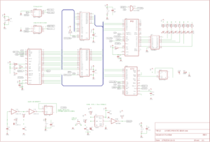
Let’s start with the LM80C PIO and RAM project that we have already up and running and let’s add our CTC. We’ll realize this circuit:
We’ll use the free side of the 7474 D-type flip flop that we used for the clock divider as the signal trigger to pilot the LED. We’ll also use another line of the 74139 decoder we used to select the PIO: as I said in the previous article, we would have used that chip soon. To use the 74139 to select between the two peripheral chips we just have to connect the /CE pin of the CTC to pin 11 of the decoder: thanks to this simple wiring, we will be able to choose either the PIO or the CTC by simply setting the A4 pin to 0 or 1, respectively. Then we’ll wire the control pins to the corresponding pins of the CPU. The CS0 and CS1 are connected to A0 and A1 and are used to select the internal timer we want to communicate to. As you can see in the picture above, there is a wire between TO0 and TRG1: as I said previously, we can daisy chain two or more timers if a count bigger than 256*256 is needed. This is the case: we have to reach a 1Hz clock so we must use 2 timers. In fact, we divide our system clock by a prescaler factor of 256 that, with the 8-bits register counter, gives us a resulting clock of approx. 56.15 Hz: 3,686,400 / 256 / 256 = 56.15 Hz. This isn’t enough. So we use the signal on the output pin as a trigger signal for the input pin of the second timer: thanks to the fact that the input clock is about 56Hz, we’ll instruct the timer to count just from 56 to 0, obtaining an output clock of 1.002Hz, very close to 1Hz (1s).
To see that the CTC works as expected, we’ll connect the trigger output pin of the second timer to the unused input of the D-type flip flop and turn on and off a LED (in this case, the output frequency will be 0.5Hz because the flip-flopping halves the input clock). Upload the code and then look at the LED that blinks independently from the LEDs driven by the PIO:
As usual, complete schematic and code are on my GitHub repository.


