During a transmission on a disturbed channel it may happen that some on the datas can be corrupted. This can happen for several reasons, like an accidental issue (an electrical interferance) or for an intentional action (someone that’s trying to violate the channel). To check the validity of the transmitted datas we usually use the checksums. A checksum is just a method to sum the single bits of the data. The simplest checksum is the algebraic sum, but it suffers of a couple of problems: it isn’t able to take over of a bits rearrangement, and it isn’t able to notice the introduction of bits of value 0. To solve these problems several algorithms have been created, one of the simplests is CRC8.
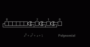
CRC is the acronym of Cyclic Redundancy Check, and it’s an algorithm that has been created by Wesley Peterson and first published in 1961. It works by introducing the input data into a logical net that has in its inside a shift register. During the shifting some bits from predefined positions are taken and combined together: the result is combined with the bit that is being inserted into the net. Some versions of this algorithm exist, with different sizes of the computed result: CRC8, that produces a checksum with a size of 8 bits, CRC16, that produces a checksum of 16 bits, and CRC32, with a checksum of 32 bits, are the most used. The image below shows how the CrC8 works (click on the image to open tha animation – source: Wikipedia):
 As we have wrote above, the CRC8 is the algorithm of the CRCx family that produces a ckechsum with the smallest size: for this reason, it is suitable only in those situations that don’t require a high levels of security. In fact, the smaller the size of the checksum the greater the chances that a collision can occur, that is ht possibility that 2 different sequences of bits produce the same checksum. But in hobbistic utilizations the CRC8 is most of the times useful enough to guarantee at least the goodness of the transmitted datas.
The proposed code is very simple. It’a function for Arduino that gets any array of bytes passed as input and returns the CRC8. The algorithm is a revisitation of the one developed by Dallas Semiconductor (now a part of the Maxim Integrated Products group) to check the datas transmitted on its 1-Wire bus.
//CRC-8 - based on the CRC8 formulas by Dallas/Maxim
//code released under the therms of the GNU GPL 3.0 license
byte CRC8(const byte *data, byte len) {
  byte crc = 0x00;
  while (len--) {
    byte extract = *data++;
    for (byte tempI = 8; tempI; tempI--) {
      byte sum = (crc ^ extract) & 0x01;
      crc >>= 1;
      if (sum) {
        crc ^= 0x8C;
      }
      extract >>= 1;
    }
  }
  return crc;
}
A couple of examples. The CRC8 of the array {3, 2, 10, 56, 23, 0} is 184 while the CRC8 of the array {2, 3, 10, 56, 23, 0} is 66: as you can see, the swapping of 2 of the values of the array produce 2 commpletely different CRC8. The same swapping won’t be detected using a simple algebraic sum.
PS: online is an old version of the function I wrote, because the previous used some optimizations that computed wrong CRCs is one or more elements of the array were 0.


I searched all over for a Java version to interface with my Arduino messages, I developed this (below) and it seems to work. Maybe some else can use it.
protected int CRC8(String stringData) {
int len = stringData.length();
int i = 0;
byte crc = 0x00;
while (len– > 0) {
byte extract = (byte) stringData.charAt(i++);
for (byte tempI = 8; tempI != 0; tempI–) {
byte sum = (byte) ((crc & 0xFF) ^ (extract & 0xFF));
sum = (byte) ((sum & 0xFF) & 0x01); // I had Problems writing this as one line with previous
crc = (byte) ((crc & 0xFF) >>> 1);
if (sum != 0) {
crc = (byte)((crc & 0xFF) ^ 0x8C);
}
extract = (byte) ((extract & 0xFF) >>> 1);
}
}
return (int) (crc & 0xFF);
}
What should I replace len value with? is it a variable ? I’m really new with arduino and still learning. Teach and explain to me please
“len” is the name of the length of the data you passed to the function when you called it. You don’t have to replace it, you need to pass it. An example of a call of the function:
returnCrc = CRC8(myData, dataLength);
To understand this you have to know some C/C++ basics. Try to find a C/C++ guide online, download it and read it. Arduino is made of hardware and software parts: you have to know both of them.