In microcontrollers, the Watchdog, literally a “watchd dog”, is a timer clocked by an indipendent oscillator. It can be set to to either send an interrupt reset or to reset the microcontroller when its counter overflows: to avoid that, the counter must be reset with a particular instruction. The therm “watchdog” indicates the function of the circuit: it is used to prevent that the system hang-ups in case of a runaway code or when an operation has run longer than expected, and it has been designed to be used in such applications where the device is put in a far or not easily accessible location and where a quick and indipendent action is required.
In this article we’ll look at the Watchdog and will learn how to use it in our applications.
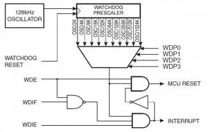
Below there’s the block diagram of the watchdog circuit as found into an ATmega328P, the microcontroller used on the Arduino UNO boards:
As we said before, the watchdog is a timer, whose internal register is incremented using a clock that is separated from the system clock of the rest of the microcontroller’s circuit. This is due to the fact that the watchdog has to run also when the system clock of the microcontroller has been halted (i.e., in a sleep mode). On the Atmel microcontrollers this clock is provided by an oscillator at 128 kHz whose signal goes through a prescaler before to be used to increment the register: the watchdog prescaler can be set to work with different values. In the ATmega328P these sets are 10, for timings between an overflow and the next that go from 16 ms to 8 s:
| # of cycles |
Interval |
| 2 K (2048) | 16 ms |
| 4 K (4096) | 32 ms |
| 8 K (8192) | 64ms |
| 16 K (16384) | 0.125 s |
| 32 K (32768) | 0.25 s |
| 64 K (65536) | 0.5 s |
| 128 K (131072) | 1.0 s |
| 256 K (262144) | 2.0 s |
| 512 K (524288) | 4.0 s |
| 1024 K (1048576) | 8.0 s |
(different chips have different prescaler values, check the datasheet of the model your’re using)
The reset of the timer is done by a special instruction, WDR, through the line marked with “WATCHDOG RES” in the diagram above. The counter of the watchdog doesn’t have a register that the user can directly access like ther other timers so the only allowed operation is the reset.
The watchdog can be used in different modes. On the ATmega328P they are 3:
- Interrupt Mode: when the counter overflows, it raises an interrupt signal that can be intercepted by a specific ISR (Interrupt Service Routine);
- System Reset Mode: when the timer overflows, the watchdog resets the microcontroller;
- Interrupt then System Reset Mode: at the fierst overflow, the watchdog raises an interrupt signal then it sets itself in System Reset Mode, so that the next overflow it will reset the system.
The first mode is useful to send an interrupt signal to routines that have run for a longer time (a sort of timeout) or to wake the microcontroller up from a deep sleep profondo (energy saving). The second one can be used to reset the microcontroller in case the code has some deadlocks in it that can block the program execution. The third way of working can be used as a secure restart system, i.e. the user could program the code to store some parameters into EEPROM before the microcontroller reset.
To use the watchdog we can follow 2 methods: the first one, more difficult, is the direct register manipulation; the second method, easier, is to use a specific library, wdt.h, that is included into the Avr toolchain. The latter is the preferred method if you aren’t an experienced user, even if it can only permits to use the watchdog in System Reset Mode, the mode that we’ll study in this first part of the guide.
To use the library, we have to include it in our sketches:
#include <avr/wdt.h>
In case you work with a standalone chip without booloader, the first instruction that must be put into the setup() is the one to deactivate the watchdog itself: in fact, the watchdog still continue to be active after the reset, so if the user doesn’t set the circuit off, the watchdog could reset the MCU forever:
void setup() {
  wdt_disable();
  ......the rest of the code here....
}
If your microcontrollers uses the Optiboot bootloader, this instruction can be omitted because this bootloader provides to disable the watchdog.
[notice]Note for the Arduino MEGA/MEGA2560 users: the bootloader of these boards doesn’t deactivate the watchdog so if you want to use the watchdog into your project you need to download a modified bootloaderf rom here. This is necessary to prevent an neverending reset of the board.[/notice]
After that, you need to set the required timeout of the watchdog with the instruction wdt_enable():
wdt_enable(timeout);
Every microcontroller has it allowed values for timeout, and are provided by library itself through predefined constants:
| WDTO_15MS |
| WDTO_30MS |
| WDTO_60MS |
| WDTO_120MS |
| WDTO_250MS |
| WDTO_500MS |
| WDTO_1S |
| WDTO_2S |
| WDTO_4S |
| WDTO_8S |
So to set a timeout of 1 second we simply write the following:
wdt_enable(WDTO_1S);
Once the watchdog has been set up, we must remember to reset its counter before the timeout expires using the following instruction:
wdt_reset();
Usually, this instruction is put at the very last position in the code block that we want to monitor, i.e. the loop(). It is the user that has to calculate the duration of the whole block and to be sure that it won’t last longer than the watchdog timeout, otherwise the microcontroller will be reset before the code meets the instruction that reset the watchdog.
Here is an example sketch tha uses the watchdog to reset the microcontroller in case the code has entered a deadlock:
#include<avr/wdt.h>void setup() { wdt_disable(); pinMode(3, INPUT); wdt_enable(WDTO_1S); } void loop() { boolean flag = true; do { if (digitalRead(3) == HIGH) { flag = false; } } while (flag); wdt_reset(); }
In this program the watchdog is used to insert a timeout to reset the chip if the pin won't change its state within 1 second.
Another usage could be use the watchdog to reset the microcontroller upon request. In this case the user just has to create a routine to call when he wants to reset the microcontroller (a reset clears the SRAM memory, reset the microcontroller registers and restore the initial state of the pins):
void reset() {
  wdt_enable(WDTO_250MS);
  while(1);
}
Just call the routine reset() from the main loop to activate the watchdog and put the code in a deadlock (while(1)), waiting for the system reset.
[important]IMPORTANT: always use timeouts that are not too short to allow the Optiboot bootloader or your code to disable the watchdog as soon as your sketch starts. I can suggest to use a time longer than 120 ms.[/important]


