One of the most annoying problems of the newset Arduino users is the serial communication, mostly the data exchange from and to the computer. People that start working with microcontrollers for the very first time doesn’t understand how datas are sent over the serial line.
In the rest of the article I’ll try to explain how to send datas from and to the PC and how let the Arduino interprete what’s coming from the external environment.
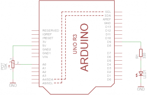
First, we need a testing circuit and a program that drives it. The testing circuit is very easy: it made by an LED with its resistor of 330/470 ohms (the value of the latter isn’t so relevant, we mostly need a LED that makes some light, not that makes a lot of light, so to drive it with a correct amount of current, choose something greater than 220 ohm, to avoid to drive the LED with a huge quantity of current, and 680 ohm, to avoid instead the opposite condition, an LED with a very low light due to undercurrent supply) connected to the PWM pin 9 of the Arduino and a potenziometer connected to the analog input A0. If you dont’ have any pot, you can also try to use a low value resistor (i.e. 100 ohm) to use it as a jumper to connect the pin A0 with the pin 5V or the 3V3 one. The circuit should be this:
Now connect your Arduino the the computer and upload the following sketch:
/* TESTING SKETCH OF BIDIRECTIONAL SERIAL COMMUNICATION
 The program receives commands from the serial and send back readings & channel states.
 To test the sketch, connect an LED to pin 9 through a resistor (330/470 ohm) and a
 potenziometer (10K) to pin A0.
 Upload the sketch, then open the serial monitor from the IDE w/a speed of 19200 bps.
 The available commands are below:
 l - reading: read the value of the input voltage on the analog pin
 a - light on: light on the LED on pin 9
 s - light off: light off the LED
 q - ask the status of the LED. The sketch will send the status of the PWM value. Possible answers:
 LED on/off/driven with a PWM signal of xxx
 w xxx - write a PWM value to the pin 9. "xxx" goes from 0 to 255. Spaces between "w" and "xxx" will be ignored. Only numeric ciphers are allowed (0..9).
 */

 //pin
 const byte inputPin = A0; //analog input pin
 const byte outputPin = 9; //output pin

 //global variables
 byte ledStatus = 0; //the status of the pin 9

 void setup() {
   Serial.begin(19200); // open the serial
   delay(1000); //wait a while to let the user the time to open the monitor
   Serial.println(F("Ready")); //I'm ready
 }

 //main program
 void loop() {
   int reading; //contains the PWM value read from the serial
   unsigned long tempMillis; //used for the timeout into the receiving block
   byte chars; //the number of chars received
   byte tempChar; //the char behind read

   //checl if something is arrived from the serial
   if (Serial.available()) {
     byte command = Serial.read(); //read the first byte
     switch (command) { //check that it's a valid command
       case 'l': //reading
         //send the reading of the analog input
         Serial.print(F("Analog reading: "));
         Serial.println(analogRead(inputPin));
         break;
       case 'a': //light on the LED
         ledStatus = 255;
         analogWrite(outputPin, ledStatus);
         Serial.println(F("LED on"));
         break;
       case 's': //light off the LED
         ledStatus = 0;
         analogWrite(outputPin, ledStatus);
         Serial.println(F("LED off"));
         break;
       case 'q': //the users want to know the status of the LED
         Serial.print(F("LED "));
         if (ledStatus == 0) {
           Serial.println(F("off"));
         } else if (ledStatus == 255) {
           Serial.println(F("on"));
         } else {
           Serial.print(F("driven with a PWM signal set to "));
           Serial.println(ledStatus, DEC);
         }
         break;
       case 'w': //set the PWM signal
         reading = 0;
         tempMillis = millis();
         chars = 0;
         //more chars are needed
         do {
           if (Serial.available()) {
             tempChar = Serial.read();
             chars++;
             if ((tempChar >= 48) && (tempChar <= 57)) { //is it a cipher? ok
               reading = (reading * 10) + (tempChar - 48);
             } else if ((tempChar == 10) || (tempChar == 13)) {
               //exit if I see a "new line" or "carriage return" char
               break;
             }
           }
         //I leave the loop for: timeout; for a PWM value greater than 255;
         //for too useless chars received
         } while((millis() - tempMillis < 500) && (reading <= 255) && (chars < 10));
         //if I received a valid PWM value, I set the pin
         if (reading <= 255) {
           ledStatus = reading;
           analogWrite(outputPin, ledStatus);
           Serial.print(F("LED on with PWM set to "));
           Serial.println(ledStatus, DEC);
         }
         break;
     }
     //now I flush the RX buffer to remove other chars I don't need
     while (Serial.available()) {
       byte a = Serial.read();
     }
   }
 }
Now, open the serial monitor of the IDE (let’s click on the “magnifier” icon put over the top right corner of the editor window) and set up a speed of 19200 bps (the same used by the sketch). Now you should receive the “Ready” message sent by the sketch that informs you the the program is up and ready to receive commands.
So, let’s start interacting with the Arduino using the following commands (commands must be written into the serial monitor and sent to the Arduino by pressing the “Enter” key):
- q – this command requests to the Arduino the status of the LED. The Arduino will answer by sending with LED on or off in case the LED is lighted up at the max light or it’s off, or will send back the value of the corresponding PWM signal (0..255).
- a – this command will light on the LED at the max intensity of light.
- s – this will light off the LED.
- l – this command will force the Arduino to read the voltage present on analog pin A0 and send this value back to the CP: so you’ll see the message “Analog reading: xxx”, with xxx that stands for a 10-bits value (0..1023) that represents the voltage that is present on the pin.
- w numer – this command is used to send to the Arduino a number that represents the PWM signal to write on the output pin 9. The number must be between 0 and 255: 0 is the same of the “light off” command while 255 is the same as “light on”. Spaces between “w” and “number” are ignored (“w10” equals to “w 10”), and so for non-numeric characters.
Let’s look at the code to understand how it works.
Less to say about the sections “pin” and “global variables”: they are just used to set the constants that will identify the pins and the variables used into the program.
Function “setup()”: it’s used to open the serial line, to wait a while and to send a “Ready” message.
Function “loop()”: this is the heart of the program. The first thing that the programm does is to check if the RX buffer of the serial line contains something, that means that the code wants to know if any character has been sent from the computer to the Arduino. The serial communication is bidirectional, so we can use the same line to send datas from the computer to the Arduino and vice versa. The Arduino has 2 serial buffers (two arrays, used to store the incoming and the outgoing datas): the function Serial.available() returns zero if no char has been received or a number representing the number of received chars. The test if (Serial.available()) is used to undestand if at least a char is into the buffer because any value greater than zero will be seen as a “true” result and the program will enter into the if-block.
Once we are sure that something is present into the buffer, we read the very first byte.
[notice]Pay attention, we’re talking about “bytes”, nor chars, values, numbers, strings, etc… the serial communications is based on sending/receiving single bytes, one after one. Every single byte can than be interpreted in different manners. For example, if we write Serial.print(“A”) then the char A will be sent, that corresponds to the byte of value 65. When we’ll receive that byte, if we’ll treat it as a char, it will correspond to the letter “A” while if we’ll treat it as a value, it will correspond to 65.[/notice]
Now the code analizes the byte to understand what’s has been received, to do this we use a switch..case.
In case a command without parameters has been received (a, s, q, l) the execution of it is easy due to the fact that we dont’ need any additional information: that command must be execute immediately, so the sketch executes the corresponding action and then it informs the user on what’s happened. This is the answering message that we receive from the Arduino on the serial monitor after we’ve sent the command.
Instead, if we want to use the command “w” we have to send another data, the value of the PWM signal we want to use to set the pin 9. As you’ve said earlier, the information that goes through the serial line is made of bytes: if we would set the PWM to 100, we simply could send a byte of value 100, and the Arduino shoudl just receive that byte and use it as the parameter to pass to the analogWrite function to change the PWM on pin 9. This, eventually, should be harder to do for the user because he first should look at an ASCII table to search for the corresponding character with value 100, that is the letter “d”, and then write it to the serial line. But, what about if the he would send the value 200? The ASCII characters are standard only in the interval from 0 to 127, after 128 every system uses its own character mapping. So the user should look for the ASCII table of his own system, then he should try to find a key combination that will reproduce that character and then he would have to write it on the serial monitor, sending it to the Arduino. Too complicated! Is there an alternative? Yes, it is. We can send that number as a string, so instead of sending a value we will send a group of bytes each representing a single characterthat forms the number. So, 200 will be break up into the single characters ‘2’, ‘0’, ‘0’ (note the quotes, in C they indicates that the character must be treated as a char). This is also the way the serial monitor sends datas, to facilitate the interaction between human and computer
So when we write “w 200” the serial monitor will send to the Arduino 5 chars: ‘w’, ‘space’, ‘2’, ‘0’, ‘0’. Our code does have just to read those characters and process them as chars. To do this we just have to keep in mind that a char as a precise ASCII code, so i.e. the space corresponds to the ASCII code 32, ‘2’ has the ASCII code 50, and so on…
The do…while loop performs this check using the ASCII codes of the characters behing received. So, to drop off the space, we just have to check if the byte has the value 32. To verify that a char is a number, we just have to look if its ASCII valus is between 48 and 57, that correspond respectively to the ciphers 0 and 9. In the program we could also have did that check using the chars instead of the values with no change. So
if ((tempChar >= 48) && (tempChar <= 57))
could be changed with
if ((tempChar >= '0') && (tempChar <= '9'))
having the same result because the compiler will create the same executable code. senza che il risultato cambi perché il compilatore crea lo stesso identico codice eseguibile. The do..while loop has a timeout too, to avoid that the code could be freeze if the serial line, for any reason, will be interrupted during the data transmission. The code accepts only ciphers and discharges spaces. The loop ends when one of the following condition is true: timeout; a number greater than 255; more than 10 useless chars are received. The conversion between char and number is made using the ASCII codes too: we knoe that 48 stands for ‘0’, 49 stands for ‘1’, 50 stands for ‘2’, etc.. so to have the value of the char behing received we just have to subtract 48, so: (48-48)=0, (49-48)=1, (50-48)=2 etc…
If the number is correct (range 0..255), we then write to the pin 9 with the function analogWrite that sets the PWM signal, and then we store into a variable for other uses. After this, we proceed to flush the RX buffer deleting any other character the Arduino could have received (let’s imagine a joker user that tries to sends “w fdsahjawknglkangw”). The previous versions of the IDE contained a function called Serial.flush() that did this work but sinc versione 1.0 it has been changed and now it wait until the TX buffer has been emptied, so I wrote a simple loop that reads all the remaining chars and store them into a local variable that will be destroyed after the sketchs leaves the do..while loop.
Here is an example of the output of the program:
In a future article we’ll see how to create a simple communication protocol to let 2 Arduino boards (or 2 microcontrollers) interact together via a serial line.


Buongiorno Leonardo, Mi chiamo Alessio e ho un quesito da proporti: Io sto lavorando con un progetto con due Arduino UNO: il primo lo uso con dei led a infrarossi con il quale invio il segnale (TX), il secondo arduino è collegato con un ricevitore TSOP che riceve il segnale e attraverso il monitor segnale mi tira fuori dei codici esadecimali (RX). ora il mio step successivo è quello di mandare dei messaggi testuali dall’arduino TX all’arduino RX. Hai qualche consiglio da darmi? Devo utilizzare la comunicazione seriale?
Ti ringrazio in anticipo
a presto
Alessio
Puoi spedire i dati sia sulla seriale che via I2C. Uno vale l’altro. Tieni conto che se su un Arduino usi la seriale per comunicare col PC, quel canale non puoi usarlo per comunicare con un altro dispositivo seriale per cui o usi la SoftwareSerial oppure, come detto, la I2C.
Ciao leonardo, ho controllato, sia per quanto riguarda la software Serial che la i2c per la comunicazione e mi permette effettivamente di comunicare con due arduino. Però ho notato che i due arduino devono essere collegati attraverso dei pin, quindi attraverso dei cavi che li collegano. Siccome io devo utilizzare questo progetto come comunicazione wireless e quindi stare in una distanza tra i 4-5 metri, risulta complicato collegarli in questo modo tramite dei cavi. C’è un modo, una libreria, un qualcosa che mi permette di comunicare dei dati ttra due arduino UNO senza collegarli ”fisicamente”? Spero di essere stato chiaro nell’esplicitare il mio problema grazie per l’aiuto e a presto
Più che una libreria, ti serve un “mezzo”. Le schedine xbee sono fatte apposta per creare piccole reti wireless seriali.
Ciao Leonardo,
sono Giacomo, un dottorando in Agraria e vorrei fare un progetto per comandare un fermentatore con Arduino e un programma in Visual Basic e monitorare i processi, ma ho dei problemi di comunicazione tra Arduino e il computer. inizialmente ho provato con il protocollo Firmata (ho messo insieme simple analog e simple digital firmata perché firmata normale non mi funzionava) e funzionava bene ma dopo qualche minuto (a volte secondo) si interrompeva la comunicazione e si bloccava tutto (ho anche provato a cambiare il “sampling interval a 99, come precisato nel sito). Uso Arduino Mega 2560 e Visual Basic Express 2010.
Ho anche provato a fare un protocollo apposta, ma sia Arduino e Visual Basic sono molto lenti e non sempre rispondono ai comandi, forse per via della grande mole di dati che scambiano i due componenti (valori di pH, temperatura, flussi e stato dei relè, e sensori).
Avresti qualcosa da suggerirmi?
Sai di qualche altro protocollo che possa fare al caso mio?
Ti ringrazio fin da subito per la pazienza per leggere tutto questo e per il preziosissimo aiuto che eventualmente mi puoi dare.
P.S. la programmazione non è proprio il mio ambiente, ma mi attira molto e sto studiando per capire in tutti i modi come poter risolvere questo problema.